


About Us
Executive Editor:Publishing house "Academy of Natural History"
Editorial Board:
Asgarov S. (Azerbaijan), Alakbarov M. (Azerbaijan), Aliev Z. (Azerbaijan), Babayev N. (Uzbekistan), Chiladze G. (Georgia), Datskovsky I. (Israel), Garbuz I. (Moldova), Gleizer S. (Germany), Ershina A. (Kazakhstan), Kobzev D. (Switzerland), Kohl O. (Germany), Ktshanyan M. (Armenia), Lande D. (Ukraine), Ledvanov M. (Russia), Makats V. (Ukraine), Miletic L. (Serbia), Moskovkin V. (Ukraine), Murzagaliyeva A. (Kazakhstan), Novikov A. (Ukraine), Rahimov R. (Uzbekistan), Romanchuk A. (Ukraine), Shamshiev B. (Kyrgyzstan), Usheva M. (Bulgaria), Vasileva M. (Bulgar).


Engineering
 PDF
PDFAbstract — The increasing popularity of a so called transient motor current signature analysis requires the fault diagnostics parameters which could not be exposed to other factors irrelevant to the fault to make a precise assessment of the failure severity level. This challenging task needs a precise modeling of faulty motor behavior in various operating conditions at different fault severity levels. This paper introduces a new approach to a finite element analysis of an induction motor with broken rotor bars during startup. The approach is based on the principle of superposition and contributes to examination of the fault rotor backward rotating magnetic field and current components produced by such field separating them from stator currents. It gives a new sight on the behavior of a faulty motor during startup for the diagnosis purposes. Further analysis of the simulation data by means of the Extended Park’s Vector Approach and the continuous wavelet transform and its experimental validation is also represented in the paper.
Fig. 1 depicts the comparison between the starting current of phase A of the faulty machine from FaultyMotorSim and estimated rotor failure current components from SuperposPrincSim2. As it can be observed the amplitude of additional components is much less than the amplitude of the fundamental supply frequency component that makes it difficult to distinguish between a healthy motor and a faulty one with broken rotor bars. The problem of masking of the fault signatures by a strong fundamental component is widely studied in the literature. As a solution, in [11] an adaptive notch filter and in [28] a bandpass filter are applied to remove the fundamental frequency from the stator current. In [15] a discrete wavelet transform (DWT) is used to extract the left sideband harmonic from the starting current. The other method in [16] involves an envelope extraction technique. An interesting method based on the reference frame theory approach is proposed in [29]. However, the approach used in [29] requires a precise speed measurement and cannot be applied for speed sensorless drive systems. The filtering out of the fundamental component in the stator current cannot be used either, since it can affect additional current components and thus can lead to incorrect results. Another approach that does not affect additional components or require speed measurement has been used in the following sections. This approach is based on examination of the Park’s vector magnitude and known as the Extended Park’s Vector Approach (EPVA) [30].
Park’s transformation is used to transform instantaneous stator currents from the three-phase system (a-b-c) to the two-phase system (d-q). The expressions for the transformation are:
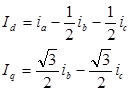 (1)
(1)
The expression for the Park’s vector magnitude (PVM) is
![]() (2)
(2)
Thus the EPVA converts three-phase stator current to equivalent DC value, which can be easily filtered out from the original signal and additional components can therefore show up more clearly.
Fig. 2 shows the PVM of FE simulated startup transient for the cases of healthy and faulty motors. As one can notice, the waveform of the faulty motor curve is slightly distorted due to additional current components caused by two broken bars. ,
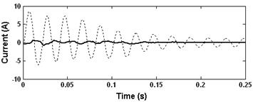
Figure 1. The starting current of a faulty motor with 2 broken bars (dotted) and estimated rotor fault additional current components (solid).

Figure 2. The PVM of the simulated startup transient of a healthy motor (top) and a faulty motor with two broken rotor bars (bottom).
Current components shown in Fig. 1 have been transformed using (1) and (2) and the resulting curve is depicted in Fig. 3. The comparison between starting currents of the faulty machine and estimated rotor failure current components after applying the EPVA is shown in Fig. 4. Comparing Figs. 1 and 4 and taking into account that the DC component of the PVM of the supply current can be easily eliminated the advantage of this approach for broken bars detection is quite evident though it requires the measurement of at least two stator currents (the third is obtained as a sum of the first two).

Figure 3. The PVM of rotor fault additional current components.
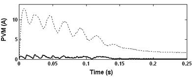
Figure 4. The PVM of a faulty motor with 2 broken bars during startup (dotted) and the PVM of rotor fault additional current components (solid).
The study in this section is focused on additional current components caused by a set failure estimated using the FE simulation and the superposition principle in the previous section and its influence on the stator currents during startup. It can be shows that the rotor fault components determined by (1) appear in the PVM at the frequency:
fPIrotorbar = 2sf1 (3)
According to (3) at the beginning of the startup the frequency of these components is maximum and equals to 100Hz. As the slip changes during startup the frequency decreases and becomes almost zero in a steady state. The corresponding frequency evolution is shown in Fig. 5(a).
The startup transient is a non-stationary process. One of the most powerful tools for a non-stationary or time varying signal analysis is a Wavelet Transform [31]-[33], providing some advantages if compared to other signal processing methods like Fourier Transform and Short-Time Fourier Transform. In the last few years several authors have focused their efforts on the applying this tool for the diagnosis of broken rotor bars. The applying of DWT has been widely discussed for current analysis during startup [8], [10], [11], [14], under speed and load torque variations [34]-[36] and during plugging stopping [10]. A contribution based on wavelet ridge was presented in [13]. In [16] the continuous wavelet transform (CWT) is used for the envelope analysis of the starting current. The Wavelet Transform can be considered as filtering out a signal with several bandpass filters while each of them extracting the components within the particular frequency range and thus representing the signal in both time and frequency domains.
As it was previously pointed out, the bar breakage produces rotor backward rotating field. According to (2) at the time point when the value of the machine slip decreases to 0.5, the backward rotating field changes its direction with respect to the stator. As at this time the speed of the rotating field equals to zero, the rotor failure therefore exerts a minimum influence on the stator currents (Fig. 5(b)). Further analysis shows that the change of the direction of the field rotation also causes the change of the behavior pattern of the additional current components induced by that field. In this connection it is suggested that the startup should be divided into two zones in the time domain (Fig. 5(c)). First zone, hereinafter a zone of high slip, corresponds to the machine slip range from 1 to 0.5. Second zone, hereinafter a zone of low slip, has the slip range from 0.5 to the steady state value.
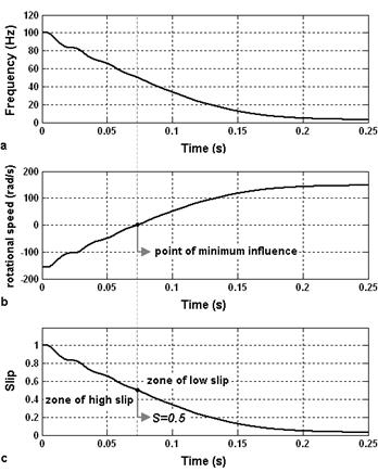
Figure 5. (a) The theoretical frequency evolution of the PVM of the left and right sideband harmonics. (b) Speed of the backward rotating rotor magnetic field. (c) The machine slip.


Figure 6. The CWT spectrograms of the PVM of the simulated fault additional components for the frequency range from 20 to 60 Hz (top) and from 60 Hz to 110 Hz (bottom).
Fig. 6 shows spectrograms of the PVM of the rotor fault components obtained by the CWT, demonstrating different behavior patterns in the frequency domain for different machine slip ranges. It can be observed that these patterns correspond to the theoretical frequency evolution of 2sf1 component in the starting PVM signal displayed in Fig. 5(a) which proves that the left and right sideband harmonics prevail over the other fault components in the specified frequency range. Regarding the amplitude pattern, as it was expected, the wavelet coefficient values decrease when the rotor fault magnetic field changes its direction i.e. when the slip equals to 0.5. The frequency and amplitude patterns presented in Fig. 6 also agree with issues previously reported in [7], [10], [14], [15] and [26].
The more wavelet coefficient values in the specified time and frequency range, the more power carried by fault components is concentrated in such range and ultimately it is more clearly that they appear in the PVM signal. Figs. 7 and 8 depict wavelet spectrograms of PVM signals shown in Fig. 2. These figures demonstrate how the characteristic patterns introduced by fault components influence the spectrogram waveform of the motor with two broken bars. Comparing these spectrograms, it can be noticed that though in the zone of low slip the differences are not significant, they are quite evident in the zone of high slip. The presence of two broken rotor bars in the machine and
healthy motor

motor with two broken rotor bars
Figure 7. The CWT spectrograms of the simulated PVM of a healthy motor (top) and a faulty motor with 2 broken rotor bars (bottom) during startup (frequency range 20-60Hz).
therefore occurrence of the fault components in the stator current increase the ripple of wavelet coefficients in the selected area of the zone of high slip that can be used for detection of the fault.
A practical remark should be made. The CWT is preferred in this study only to facilitate the understanding of the examined phenomenon since it provides more flexible analysis comparing to DWT. On the other hand, the CWT requires higher computing power as compared to DWT because information provided by the CWT is highly redundant. Therefore, for industrial applications the DWT will be a more reasonable choice.
healthy motor

motor with two broken rotor bars
Figure 8. The CWT spectrograms of the simulated PVM of a healthy motor (top) and a faulty motor with 2 broken rotor bars (bottom) during startup (frequency range 60-110Hz).
In order to validate the simulation results several experiments have been performed. The motor used in experiments is identical to the simulated one (4 poles, 29 rotor bars, 380 V, 0.5 kW, 50 Hz) and tested in the same conditions. Two line currents are captured using a PC-based data acquisition system with a sampling frequency of 8 kHz. The motor is started at no load in healthy conditions and with a faulty rotor that has two and four broken bars. The bars are broken by drilling a hole in them.

Figure 9. The experimentally measured PVM of (a) a healthy motor, (b) a faulty motor with 2 broken rotor bars and (c) a faulty motor with 4 broken rotor bars during startup.
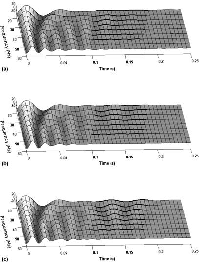
Figure 10. The CWT spectrograms of the experimentally measured PVM of (a) a healthy motor, (b) a faulty motor with 2 broken rotor bars and (c) a faulty motor with 4 broken rotor bars during startup (frequency range 20-60Hz).

Figure 11. The CWT spectrograms of the experimentally measured PVM of (a) a healthy motor, (b) a faulty motor with 2 broken rotor bars and (c) a faulty motor with 4 broken rotor bars during startup (frequency range 60-110Hz).
Fig. 9 shows the experimentally measured PVM signals of the healthy motor and the motor with two and four broken bars during a startup transient. The obtained data has been processed using the CWT of the Matlab Wavelet Toolbox. The resulting wavelet spectrograms are displayed in Figs. 10 and 11. As follows from figures, these spectrograms show the behavior patterns similar to those displayed in Figs. 7 and 8 for simulated results. The healthy motor (Figs. 10(a) and 11(a)) shows some initial ripple of the wavelet coefficients of the selected areas in both high and low slip zones due to the intrinsic rotor asymmetry. As it was predicted by the modeling in previous sections the breakage of two bars (Figs. 10(b) and 11(b)) increases the ripple of wavelet coefficients in the zone of high slip and slightly influences the spectrogram waveform in the zone of low slip. Moreover, the drilling of two additional bars (Figs. 10(c) and 11(c)) leads to subsequent increase in the ripple of wavelet coefficients not only in the high slip zone but also in the zone of low slip.
This paper presents a new approach to precise modeling of an induction motor with broken rotor bars during startup providing a deep understanding of the fault related phenomenon for diagnostic purposes. The principle of superposition explaining behavior of a faulty rotor induction machine in a steady-state has been extended and applied for the startup. It is shown that the combination of the superposition principle with the time-stepping finite element method provides accurately estimated stator current components caused by the rotor failure. It can be used to establish the fault severity quantification parameters independent of motor operating conditions, a chosen signal processing tool and other factors not related to the rotor failure, which are considered as future work in this study. The validation of the proposed approach shows a good agreement with the experimental results as well as with the issues previously reported in the technical literature.
The method combining the wavelet transform with the Extended Park’s Vector Approach has been used for analysis of the simulated and experimental data. It is shown that the Extended Park’s Vector Approach allows improving the sensitivity of the wavelet transform for rotor faults detection comparing to methods involving only one line current as input due to its inherent ability to eliminate the stator current fundamental frequency component. However, its implementation requires a measurement of one additional line current and the choice of the single-current or two-current diagnostic approach is a matter of a reasonable balance between the cost and reliability of the diagnostic system.
REFERENCES
- Thomson, W. T. and M. Fenger, “Current signature analysis to detect induction motor faults,” IEEE Industry Applications Magazine, vol. 7, no. 4, 26-34, Jul./Aug. 2001.
- Kliman, G. B. and J. Stein, "Induction motor fault detection via passive current monitoring,” in Proc. of Int. Conf. Electrical Machines (ICEM'90), 13-17, 1990.
- Nandi, S. and H. A. Toliyat, “Condition monitoring and fault diagnosis of electrical machines – A Review,” in Proc. of Industry Applications Conference, vol. 1, 197 - 204, 1999.
- Kliman, G. B., R. A. Koegl, J. Stein, R. D. Endicott, M. W. Madden, “Noninvasive detection of broken rotor bars in operating induction motors,” IEEE Trans. Energy Convers., vol. 3, no. 4, 873-879, Dec. 1998.
- Elkasabgy, N. M., A. R. Eastham, G. E. Dawson, “Detection of broken rotor bars in the cage rotor on an induction machine,” IEEE Trans. Ind. Appl., vol. 28, no. 1, 165-171, Jan./Feb. 1992.
- Bellini, A., F. Filippetti, G. Franceschini, C. Tassoni, G. B. Kliman, “Quantitative evaluation of induction motor broken bars by means of electrical signature analysis,” IEEE Trans. Ind. Appl., vol. 37, no. 5, 1248-1255, Sep./Oct. 2001.
- Garcia-Perez, A., R. J. Romero-Troncoso, E. Cabal-Yepez, R. A. Osornio-Rios, J. de Jesus Rangel-Magdaleno, H. Miranda, “Startup current analysis of incipient broken rotor bar in induction motors using high-resolution spectral analysis,” in Proc. of IEEE Int. Symposium on Diagnostics for Electric Machines, Power Electronics & Drives, 657 – 663, Sept. 2011.
- Kechida, R., A.Menacer, “DWT wavelet transform for the rotor bars faults detection in induction motor,” in Proc. of 2nd Int. Conf. On Electric Power and Energy Conversion Systems, 1 – 5, Nov. 2011.
- Keskes, H., A. Braham, Z. Lachiri, “Broken rotor bar diagnosis in induction machines through Stationary Wavelet Packet Transform under lower sampling rate,” in Proc. of 1st Int. Conf. On Renewable Energies and Vehicular Technology, 452 – 459, March 2012.
- Riera-Guasp, M., J. A. Antonino-Daviu, M. Pineda-Sanchez, R. Puche-Panadero, J. Perez-Cruz, “A general approach for the transient detection of slip-dependent fault components based on the discrete wavelet transform,” IEEE Trans. Ind. Electron., vol. 55, no. 12, 4167 - 4180, Dec. 2008.
- Douglas, H., P. Pillay, and A. K. Ziarani, "A new algorithm for transient motor current signature analysis using wavelets," IEEE Trans. Ind. Appl., vol. 40, no. 5, 1361 – 1368, Sep./Oct. 2004.
- Faiz, J., B.-M. Ebrahimi, “A new pattern for detecting broken rotor bars in induction motors during start-up,” IEEE Trans. Magn., vol. 44, no. 12, 4673 - 4683, Dec. 2008.
- Zhang, Z., Z. Ren, and W. Huang, "A novel detection method of motor broken rotor bars based on wavelet ridge," IEEE Trans. Energy Convers., vol. 18, no. 5, 417-423, Sept. 2003.
- Ordaz-Moreno, A., R. de Jesus Romero-Troncoso, J.A. Vite-Frias, J.R. Rivera-Gillen, A. Garcia-Perez, “Automatic online diagnosis algorithm for broken-bar detection on induction motors based on discrete wavelet transform for FPGA implementation,” IEEE Trans. Ind. Electron., vol. 55, no. 5, 2193 - 2202, May 2008.
- Pineda-Sanchez, M., M. Riera-Guasp, J.A. Antonino-Daviu, J. Roger-Folch, J. Perez-Cruz, R. Puche-Panadero, “Instantaneous frequency of the left sideband harmonic during the start-up transient a new method for diagnosis of broken bars,” IEEE Trans. Ind. Electron., vol. 56, no. 11, 4557 - 4570, Nov. 2009.
- Supangat, R., N. Ertugrul, W.L. Soong, D.A. Gray, C. Hansen, J. Grieger, “Broken rotor bar fault detection in induction motors using starting current analysis,” in Proc. of European Conf. On Power Electronics and Applications, 1-10, 2005.
- Aroui, T., Y. Koubaa, A. Toumi, “Magnetic coupled circuits modeling of induction machines oriented to diagnostics,” Leonardo Journal of Sciences, vol. 7, no. 13, 103-121, July-Dec. 2008.
- Sprooten, J., J. Gyselinck, J.-C. Maun, “Comparison of models of faulty induction motors: performances and applications,” in Proc. of IEEE Int. Symposium on Diagnostics for Electric Machines, Power Electronics & Drives, 132 - 137, Sept. 2007.
- Zhang, L. and T. S. Cheang, “Two new approaches to analysis of inner-fault of squirrel-cage rotor for three-phase induction motors,” in Proc. of 5th Int. Conf. On Electrical Machines and Systems, vol. 1, 51 – 55, 2001.
- Samonig, M.A., P. Nussbaumer, G. Stojicic, T.M. Wolbank, “Analysis of rotor fault detection in inverter fed induction machines at no load by means of finite element method,” in Proc. of 37th Annual Conf. on IEEE Ind. Electron. Society, 1758 – 1763, Nov. 2011.
- Zouzou, S.E., S. Khelif, N. Halem, M. Sahraoui, “Analysis of induction motor with broken rotor bars using finite element method,” in Proc. of 2nd Int. Conf. On Electric Power and Energy Conversion Systems, 1-5, Nov. 2011.
- Sprooten, J., J. Gyselinck, J.C. Maun, “Local and global effect of a broken bar in induction machines using fundamental electromagnetic laws and finite element simulations,” in Proc. of IEEE Int. Symposium on Diagnostics for Electric Machines, Power Electronics & Drives, 1 - 6, Sept. 2005.
- Kuptsov, V.V., A.S. Sarvarov, A.S. Gorzunov, “Development of current signature analysis technique to detect faults in induction motors by oscillograms of unsteady-state machine operation,” Vestnik Yuzhno-Ural'skogo Gosudarstvennogo Universiteta. Seriya Energetika, vol. 34, no. 12, 60 - 67, Jun. 2009 (in Russian).
- Faiz, J., B. M. Ebrahimi, and M. B. B. Sharifian, "Time stepping finite element analysis of broken bars fault in a three-phase squirrel-cage induction motor," Progress In Electromagnetics Research, Vol. 68, 53-70, 2007.
- 25. Vaseghi, B., N. Takorabet, and F. Meibody-Tabar, "Transient finite element analysis of induction machines with stator winding turn fault," Progress In Electromagnetics Research, Vol. 95, 1-18, 2009.
- Riera-Guasp, M., J.A. Antonino-Daviu, J. Roger-Folch, M.P. Molina Palomares, “The Use of the Wavelet Approximation Signal as a Tool for the Diagnosis of Rotor Bar Failures,” IEEE Trans. Ind. Appl., vol. 44, no. 3, 716-726, May./Jun. 2008.
- Deleroi, W., “Squirrel cage motor with broken bar in the rotor – physical phenomena and their experimental assessment,” in Proc. of Int. Conf. On Electrical Machines, 767-770, 1982.
- Bouzida, A., O. Touhami, R. Ibtiouen, A. Belouchrani, M. Fadel, A. Rezzoug, “Fault diagnosis in industrial induction machines through discrete wavelet transform,” IEEE Trans. Ind. Electron., vol. 58, no. 9, 4385 – 4395, Sept. 2011.
- Ak?n, B., S. Choi, U. Orguner and H. A. Toliyat, “A simple real-time fault signature monitoring tool for motor drive embedded fault diagnosis systems,” IEEE Trans. Ind. Electron., vol. 58, no. 5, 1990-2001, May 2011.
- Cruz, S. M. A. and A. J. Marques Cardoso, ”Stator winding fault diagnosis in three-phase synchronous and asynchronous motors, by the extended Park’s vector approach,” IEEE Trans. Ind. Appl., vol. 37, no. 5, 1227-1233, Sept./Oct. 2001.
- Daubechies, I., "The wavelet transform, time-frequency localization and signal analysis," IEEE Trans. Information Theory, vol. 36, no. 5, 961-1005, Sep. 1990.
- Mallat, S., A Wavelet Tour of Signal Processing. San Diego, CA: Academic, 1999.
- Misiti, M., Y. Misiti, G. Oppenheim, and J. M. Poggi, Wavelet Toolbox, User’s Guide for Matlab. Natick, MA: MathWorks, Jun. 2004.
- Abu-Rub, H., A. Iqbal, S.K.M. Ahmed, J. Guzinski, M. Adamowicz, M. Rahiminia, “Rotor broken bar diagnostics in induction motor drive using Wavelet packet transform and ANFIS classification,” in Proc. of Int. Conf. On Electric Machines & Drives Conference, 365 – 370, May 2011.
- Cusido, J., L. Romeral, J.A. Ortega, J.A. Rosero, A. Garcia Espinosa, “Fault detection in induction machines using power spectral density in wavelet decomposition,” IEEE Trans. Ind. Electron., vol. 55, no. 2, 633 - 643, Feb. 2008.
- Sadeghian, A., Zhongming Ye, Bin Wu, “Online detection of broken rotor bars in induction motors by wavelet packet decomposition and artificial neural networks,” IEEE Trans. Instrum. Meas., vol. 58, no. 7, 2253 - 2263, July 2009.
M.U. Petushkov ANALYSIS OF DEFECTS IN THE ROTOR ASYNCHRONOUS MOTOR DURING START . International Journal Of Applied And Fundamental Research. – 2013. – № 1 –
URL: www.science-sd.com/452-24043 (18.04.2024).