


About Us
Executive Editor:Publishing house "Academy of Natural History"
Editorial Board:
Asgarov S. (Azerbaijan), Alakbarov M. (Azerbaijan), Aliev Z. (Azerbaijan), Babayev N. (Uzbekistan), Chiladze G. (Georgia), Datskovsky I. (Israel), Garbuz I. (Moldova), Gleizer S. (Germany), Ershina A. (Kazakhstan), Kobzev D. (Switzerland), Kohl O. (Germany), Ktshanyan M. (Armenia), Lande D. (Ukraine), Ledvanov M. (Russia), Makats V. (Ukraine), Miletic L. (Serbia), Moskovkin V. (Ukraine), Murzagaliyeva A. (Kazakhstan), Novikov A. (Ukraine), Rahimov R. (Uzbekistan), Romanchuk A. (Ukraine), Shamshiev B. (Kyrgyzstan), Usheva M. (Bulgaria), Vasileva M. (Bulgar).


Phisics and Mathematics
 PDF
PDFAn evidence-based selection of the magnetic core shapes and sizes based on electrical calculation of its design value parameters is required when designing apparat uses implementing electromagnetic method of creating grinding effort in order to ensure within the scope of product processing required by technology energy and power factors of grinding process. The major factor of adjustment by power and energy interactions among the magnetic field, operating elements and processed product in EMMA is making proportionality of value change of magnetic field В induction (or magnetic flow Ф) within the scope of processing and at some certain segments of magnetic core to excitation current Iу in the gate windings (i.e. ensuring unites operating conditions with the materials unsaturated magnetic state of its magnetic core).
If we accept as a base of EMMA design shape its traditional cylindrical design of working space with the gate winding in the unit frame[1,2,3,4], then magnetic flow Ф making by electric current flowing through the winding of GW is closed at the segments of magnetic core – frame I, working space II and inner cylinder (rotor III) (Fig.1). Due to cylindrical design of the surfaces limiting working space the frame section area is considerably small in comparison to the inner cylinder section area; magnetic induction ВК in the frame has larger value in comparison to cylinder. As far as the frame width is insignificant comparing to its outer radius, one may consider that magnetic flow is evenly distributed over its thickness.
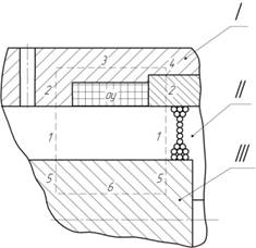
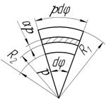
Fig.1-Structural design of EMMA magnetic core:
I, 2, …, 6 –magnetic core segments; GW – gate winding; I – frame; II – working space with ferrospheres; III – inner cylinder
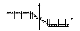
As it evidences from the diagram of magnetic field Н0 intensity distribution inside of the working space (Fig. 2) the magnetic flow Ф of the first unit part flows into frame and goes into product processing amount in its second part. To find maximum permitted induction value of magnetic flow in the frame![]() (and, with allowance made for this value, to find rational adjustment range), one should integrate induction value in the working space at the frame inner surface(at
(and, with allowance made for this value, to find rational adjustment range), one should integrate induction value in the working space at the frame inner surface(at![]() , where
, where ![]() - radius of the processing amount point, R1 –inner frame radius) by half of this surface and to divide the result in minimum section area of frame Sк. Provided that magnetic flow Фin the unit frame can be given as follows:
- radius of the processing amount point, R1 –inner frame radius) by half of this surface and to divide the result in minimum section area of frame Sк. Provided that magnetic flow Фin the unit frame can be given as follows:
![]() , (1)
, (1)
where ![]() - magnetic inductive capacity of working space filler. To define intensity value of magnetic field Н0 at the inner surface of frame (at
- magnetic inductive capacity of working space filler. To define intensity value of magnetic field Н0 at the inner surface of frame (at![]() ) let us examine field structure at some certain „α“ and „l-α“ segments of the unit working space (Fig. 2 and 3).
) let us examine field structure at some certain „α“ and „l-α“ segments of the unit working space (Fig. 2 and 3).
At ![]() segment (Fig. 2) the field in the working space of EMMA of cylindrical design is equally radial, provided that its value parameters (intensity and induction) increase in the units radius to the inner cylindrical surface being operating volume under linear law.
segment (Fig. 2) the field in the working space of EMMA of cylindrical design is equally radial, provided that its value parameters (intensity and induction) increase in the units radius to the inner cylindrical surface being operating volume under linear law.
It is possible to demonstrate the first conclusion based on the Ampere's circuital law:
![]() , (2)
, (2)
by its application to two closed circuits dlС intensity vector Н circulation (circuits I and 2 are specified in Fig.3 as dash lines).
а)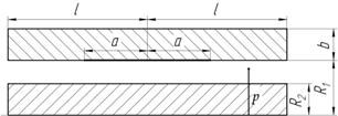
 b)
b)
Fig. 2 – Calculated segments of EMMA elements:
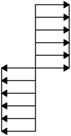
а – segments geometries; b – allocation scheme of the magnetic field flux lines in working space of EMMA; 2l –working space height;
2а – groove width to place gate winding; в- frame width; R1 and R2 –radiuses of cylindrical surfaces of frame and rotor, accordingly; ρ- radius of working space random point
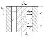
a) b) c)
Fig. 3 –Scheme to calculate the value parameters of electromagnetic field at the segment „l-α“of working space:а – unit vertical section; b –working space element; c – allocation scheme of the magnetic field flux lines at „l-α“segments
For this purpose let us have the following believe: unit end caps are made of non-magnetic material; rotor and frame are produced from ferromagnetic material with high value of magnetic inductive capacity![]() ; let us admit
; let us admit![]() (in this case magnetic flow enters the ferromagnetic material surface at right angle, i.e.by working space radii); the entire magnetic field is concentrated within the working space, provided that we neglect edge effects; electric current is idealized by a single loop ω with zero cable diameter and current i, i.e. we neglect electric field energy and energy dissipation in the winding grooves.
(in this case magnetic flow enters the ferromagnetic material surface at right angle, i.e.by working space radii); the entire magnetic field is concentrated within the working space, provided that we neglect edge effects; electric current is idealized by a single loop ω with zero cable diameter and current i, i.e. we neglect electric field energy and energy dissipation in the winding grooves.
Under these assumptions the magnetic field НК intensity in ferromagnetic material elements has zero value![]() and, hence, in parts of magnetic flow the I and 2 path lines running in ferromagnetic material an integral of the expression (2) shall also be equal to zero. There are only parts of the I and 2 paths lines running in working space by the units radii under the integral sign. Replacing magnetic field intensity in the working space along the radius with mean value of НСР, one may go from an integral in the Ampere's circuital law to algebraic expressions. The following equations are correct for the I and 2 path lines:
and, hence, in parts of magnetic flow the I and 2 path lines running in ferromagnetic material an integral of the expression (2) shall also be equal to zero. There are only parts of the I and 2 paths lines running in working space by the units radii under the integral sign. Replacing magnetic field intensity in the working space along the radius with mean value of НСР, one may go from an integral in the Ampere's circuital law to algebraic expressions. The following equations are correct for the I and 2 path lines:![]() ,
,
![]() (where h0 is working space width). Comparison of these two equations reveals that
(where h0 is working space width). Comparison of these two equations reveals that![]() . Magnetic field intensity module in processing amount does not change heightwise. Data obtained verifies that magnetic field in the working space of EMMA of cylindrical design is equally radial and intensity mean value is defined by representation as follows:
. Magnetic field intensity module in processing amount does not change heightwise. Data obtained verifies that magnetic field in the working space of EMMA of cylindrical design is equally radial and intensity mean value is defined by representation as follows:
![]() . (3)
. (3)
By radius of the working space magnetic field intensity increase by linear law from outer to inner lateral surface. To verify this assumption we use law of magnetic flow continuity where under magnetic flow Ф2 coming out of the top half of unit inner part is equal to magnetic flow Ф1 entering the top half of the outer part of the frame Ф1=Ф2. Hence, the expressions to define magnetic flows appear as follows:
![]() ,
,![]() or
or![]() ,
,![]() (whereB1 , H1иВ2, Н2 – magnetic field intensity induction on, accordingly, outer and inner cylindrical surfaces of the working space). It goes from the provided expressions that
(whereB1 , H1иВ2, Н2 – magnetic field intensity induction on, accordingly, outer and inner cylindrical surfaces of the working space). It goes from the provided expressions that
![]() и
и![]() , (4)
, (4)
i.e. basic value parameters of magnetic field in processing amount increase by radius to inner surface forming processing amount by linear law.
Simultaneous solution of equations (3) and (4) allow obtaining expressions to define intensity Н0 and induction В0 of magnetic field at any point of working space:
![]() , (5)
, (5)
![]() , (6)
, (6)
where ρ- radius of processing amount point at![]() .
.
With allowance made for functional connection (6) and value parameters of the design pattern shown in Fig.2 representation to define magnetic energy![]() (whereV0 – product processing amount) at „l-α“segment can be represented as follows:
(whereV0 – product processing amount) at „l-α“segment can be represented as follows:
![]() .
.
After integration
and a number of simple mathematical transformations we obtain a formula to calculate energy in EMMA working space at „l-α“ segment:
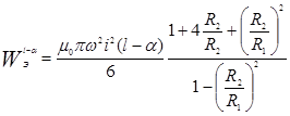 , (7)
, (7)
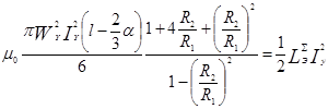
As far as magnetic energy according to data [5] is equal to ![]() (where LЭ – gate winding inductance), then with allowance made for expression (7) one may write down equation:
(where LЭ – gate winding inductance), then with allowance made for expression (7) one may write down equation:
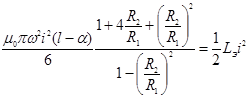
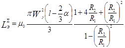
Hence we get formula to define gate winding inductance at „l-α“segment:
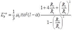 . (8)
. (8)
Formulae (7) and (8) have been obtained for the ideal case when the gate winding with current creating magnetic field in the apparatus working space is shown as one loop with zero cable diameter. However, at the arrangement the gate winding captures significant part of EMMA length. Therefore, it can be more accurately represented by current sheet symmetrically disposed relative to the middle of the working space on inner surface of the cylindrical frame. At the same time linear current density in a sheet σi is defined by representation /10/ σi=WyIy/2α, where Wy–number of loops in the gate winding; Iy- current in the winding.
At „α“ segments (Fig.2) magnetic field intensity in EMMA amounts varies linearly (for a fixed value of ρ) by law as follows:
![]() . (9)
. (9)
Magnetic energy at this segment is equal to
![]()
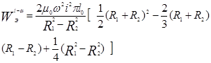
or after integration and some mathematical transformations may be represented as follows:
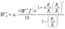 . (10)
With allowance made for expressions(7) and (10) total magnetic energy in working space ![]() at the segments „l-α“ and „α“
at the segments „l-α“ and „α“![]() is calculated by formula as follows:
is calculated by formula as follows:
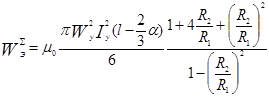 . (11)
Inductance ![]() gate winding of EMMA is defined from equation:
gate winding of EMMA is defined from equation:
 ,
,
 . (12)
Based on the data obtained magnetic flow Ф (11) running through the unit frame, may be expressed as follows:
![]() .
.
Integration of this expression as integral containing linear factors / 11 /, in the aisles between 0 and α
![]() ,
,
gives the final required equation:
![]() . (13)
. (13)
Provided that the unit frame is the most consistent segment of magnetic core in magnetic terms and based on cylindrical design of this segment one may write down
![]() . (14)
. (14)
Simultaneous solution of equations (13) and (14)
![]()
provides representation to define induction value in the unitframe:
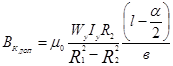 . (15)
Assessment of connections obtained reveals that when developing EMMA of cylindrical design, it is important to select minimum value ![]() in frame, i.e.at the location of the gate winding (segment 3 in Fig.1). Moreover to ensure high adjustment capacities of the frame it is important to make the production from magnetic material with high value of magnetic inductive capacity and inductance saturation. Upon determining by magnetization curves for the selected materials the most intensive segment of magnetic core
in frame, i.e.at the location of the gate winding (segment 3 in Fig.1). Moreover to ensure high adjustment capacities of the frame it is important to make the production from magnetic material with high value of magnetic inductive capacity and inductance saturation. Upon determining by magnetization curves for the selected materials the most intensive segment of magnetic core ![]() in magnetic terms, one may define maximum value of control current:
in magnetic terms, one may define maximum value of control current:
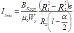 . (16)
It follows from the above that if the control of EMMA electromagnetic operational mode is performed within the range of current Iу in the windings
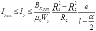 . (17)
where ![]() -minimum current value ensuring formation of structural groups made of ferromagnetic elements in the working space, then an efficient control of the force interactions magnitude between unit grinding bodies is provided and, hence, an efficient control of products dispersion process ensures as well.
-minimum current value ensuring formation of structural groups made of ferromagnetic elements in the working space, then an efficient control of the force interactions magnitude between unit grinding bodies is provided and, hence, an efficient control of products dispersion process ensures as well.
Reported research results represent methodological basis to calculate the magnetic circuit of electrical device such as EMMA of cylindrical design.
2. Bezzubtseva М.М., Volkov V.S. Mechanical activators of agroindustrial complex. Analysis, innovations, inventions: monograph. - SPb.: SPbGAU, 2014. –p. 161.
3. Bezzubtseva М.М., VolkovV.S. Applied theory of electromagnetic method of mechanical activation// Journal of International Academy of Agrarian Education. - 2013. - №16. –p. 93-96.
4. Bezzubtseva М.М., PlatashenkovI.S., Volkov V.S. Classification of electromagnetic grinders for food agricultural raw materials // JournalofSaintPetersburgStateAgrarianUniversity. - 2008. - №10. –p. 150-153.
Bezzubceva M.M., Kotov A.V. ASSESSMENT OF THE MAGNETIC FIELDS STRUCTURE IN THE WORKING SPACE OF ELECTROMAGNETIC MECHANICAL ACTIVATORS OF CYLINDRICAL DESIGN. International Journal Of Applied And Fundamental Research. – 2015. – № 1 –
URL: www.science-sd.com/460-24756 (16.04.2024).