


About Us
Executive Editor:Publishing house "Academy of Natural History"
Editorial Board:
Asgarov S. (Azerbaijan), Alakbarov M. (Azerbaijan), Aliev Z. (Azerbaijan), Babayev N. (Uzbekistan), Chiladze G. (Georgia), Datskovsky I. (Israel), Garbuz I. (Moldova), Gleizer S. (Germany), Ershina A. (Kazakhstan), Kobzev D. (Switzerland), Kohl O. (Germany), Ktshanyan M. (Armenia), Lande D. (Ukraine), Ledvanov M. (Russia), Makats V. (Ukraine), Miletic L. (Serbia), Moskovkin V. (Ukraine), Murzagaliyeva A. (Kazakhstan), Novikov A. (Ukraine), Rahimov R. (Uzbekistan), Romanchuk A. (Ukraine), Shamshiev B. (Kyrgyzstan), Usheva M. (Bulgaria), Vasileva M. (Bulgar).


Engineering
 PDF
PDFProcessing of furnaces heating records, plotting of transient response graph for object by experimental points and drawing of tangent in the field of its maximum inclination must precede estimation procedure. As a result transfer function of first heating zone has been obtained:
 (1)
(1)
Stability factor of system can be determined not only by arrangement of roots of its characteristic equation but by shape of unit-impulse response of its closed loop as well. Stability factor evaluates by subsidence ratio of oscillations which can emerge in loop. Appearance of resonance peak in plot of complex frequency response (CFR) absolute magnitude corresponds to oscillatory character of unit-impulse response. Height of resonance peak depends on degree of open loop CFR approach to “dangerous” point -1, j0. The nearer response of open loop Wo.l(jω) approaches to this point, the greater this peak turns out. Stability condition of closed loop for control systems with integral component in algorithm of controller performance looks in the following way [3]:
![]() (2)
(2)
where |Φ(jωres)| – absolute magnitude of open loop CFR; Mext – assigned beforehand permissible value of frequency index for loop oscillation, namely, relative value of CFR resonance peak.
At
determination of maximum permissible value for transfer constant of controller kt, which is situated in closed
loop of system, it is necessary to plot response Wo.l(jω) at arbitrary value of this constant and
draw circle of radius of ![]() at the same plane. Center of this circle is
located on negative real semiaxis at distance of
at the same plane. Center of this circle is
located on negative real semiaxis at distance of ![]() . Required ratio between
radius of M-circle and coordinate
of its center u looks in the
following way:
. Required ratio between
radius of M-circle and coordinate
of its center u looks in the
following way:
![]() (3)
(3)
If calculations are automatized, expression (3) can be included in calculation program and task is reduced only to matching of u value at which circle will be tangent to CFR of open loop. If it turns out that response Wo.l(jω) has hit inside “forbidden” area which is confined by this circle, it is necessary to replot it choosing greater value of u. If response passes outside the circle, it is necessary to decrease value of u [3].
In figure 1 CFR of open loop at unitary transfer constant of I controller (solid-line curve) and M-circle (dashed curve) which is tangent to it are plotted at value of M = 1,8 what corresponds to subsidence ratio of oscillations ψ = 0,85 in oscillatory link. q(ω) and qm(ω, u) are imaginary components of CFR and M-circle respectively, and p(ω) and pm(ω, u) are their real components. As a result of position matching of circle center value u = 6,628 has been obtained.
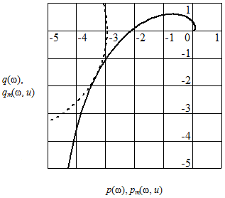
Figure 1 – CFR of open loop and М-circle
Then value of maximum permissible transfer constant of I controller for first heating zone is calculated by formula [3]:
 (4)
(4)
Value kt = 0,218 has been obtained from expression (4). Similar procedures have been executed for controllers of second heating and soaking zones. As a result of calculations limit values of tuning coefficients equal to 0,211 and 0,172 respectively have been obtained. Calculations have been carried out in MathCAD package.
Proposed stability factor estimation for I controllers will allow choosing tuning coefficients at stage of control systems designing. At these coefficients occurring in closed loops transient processes will damp most intensively.
2. Serdobintsev, Y. P. Algorithm of optimal modes calculation for slab heating in a continuous furnace / Y. P. Serdobintsev, M. P. Kukhtik // International Journal of Applied and Fundamental Research. – 2014. – No. 2. – URL: http://www.science-sd.com/457-24551
3. Rotach, V. Y. Automatic control theory: a textbook for high schools / V. Y. Rotach. – М. : MPEI Publishing house, 2008. – 396 p.
Serdobintsev Y. P., Kukhtik M. P. STABILITY FACTOR ESTIMATION OF HEATING CONTROL SYSTEM
IN A CONTINUOUS FURNACE
. International Journal Of Applied And Fundamental Research. – 2015. – № 2 –
URL: www.science-sd.com/461-24941 (18.04.2024).