


About Us
Executive Editor:Publishing house "Academy of Natural History"
Editorial Board:
Asgarov S. (Azerbaijan), Alakbarov M. (Azerbaijan), Aliev Z. (Azerbaijan), Babayev N. (Uzbekistan), Chiladze G. (Georgia), Datskovsky I. (Israel), Garbuz I. (Moldova), Gleizer S. (Germany), Ershina A. (Kazakhstan), Kobzev D. (Switzerland), Kohl O. (Germany), Ktshanyan M. (Armenia), Lande D. (Ukraine), Ledvanov M. (Russia), Makats V. (Ukraine), Miletic L. (Serbia), Moskovkin V. (Ukraine), Murzagaliyeva A. (Kazakhstan), Novikov A. (Ukraine), Rahimov R. (Uzbekistan), Romanchuk A. (Ukraine), Shamshiev B. (Kyrgyzstan), Usheva M. (Bulgaria), Vasileva M. (Bulgar).


Materials of the conference "EDUCATION AND SCIENCE WITHOUT BORDERS"
 PDF
PDF
An electron with an electric charge of ![]() generates an electric field with energy equal to 511 кеВ . To separate electron from atom (molecule) electron-volt units are required, but the directed or oscillatory motion of electrons
generates an electric field with energy equal to 511 кеВ . To separate electron from atom (molecule) electron-volt units are required, but the directed or oscillatory motion of electrons ![]() performs electromagnetic process [1].
performs electromagnetic process [1].
The design of experimental plant to test the possibility of flowing electron beam energy to electric circuit is presented by Fig. 1. The plant is constructed on the basis of electron-beam tubes (EBT) of the first, the tubes together with electron-beam gun of hot-cathode plasma generator (EGHP) - 2 creates appropriate electron plasma flow in a form of electron beam that goes to the cross electric field of polarizable electrode (PE) – 3, located in the EBT instead of electrostatic deflector. EBTs are placed in vacuum chamber (VCh) – 4, performing negative pressure not less than 6,6 . 10-3 P а . HCPG of EBT is connected with power unit (PU) – 5 of EBT. PE affects electron plasma flow by cross electric field in mode of full wave transformation of direct convection current of electron beam into alternate current of conductivity [2,3,4,5,6,7]. The produced conductivity current flows along high-voltage winding (HVW) – 6 of transformer - rectifier (T-R) – 7 (vacuum manometer transformer of VEMB-1 type is used). HVW center (C) – 8 is connected with the cathode of HCPG of EBT and it is grounded. Equalizing capacitors are linked to HVW shoulders in parallel. The capacitors neutralizes magnetic losses and eddy-current losses as well as reactive induced power, they can be used to create current resonance HVW shoulder inductance at operation frequency. Low frequency standard-voltage generator (LFG) – 11 of GZ-112 type is connected with low-voltage winding (LVW) – 10.
Current intensity in HVW, PE, and inside the anode circuit А 2 of HCPG is measured with precision resistors 12, 13, and 14 relatively, their resistance rating being 10 kΩ. Resistors are located into both arms of the plant for two reasons: the first reason is not to break electric symmetry of the experimental plant scheme and the second is to perform measurements in both EBTs and HVW arms simultaneously.
The plant functions in the following way: LFG – 11 creates actual frequency oscillations in HVW – 6. When there is negative voltage half-wave in one arm, there is positive one in the second arm, the last is fed to А 2 of HCPG - 2. Under the positive voltage half-wave impact the electron beam is directed to PE – 3, where convection current of electron beam is transformed into electric current impulse of conductivity that flows in the relevant arm of HVW. When voltage direction is changed into the opposite, electric current impulse of conductivity proportional to convection current of electric beam flows in another arm of HVW. As a result we get additional energy at actual frequency due to full-wave transformation of convection current of electron beam to the current of HVW conductivity and into relevant current intensity of transformer rectifier. The gross capacitance obtained due to the given transformation equals to electric current intensity inside the circuit (9) multiplied to actual voltage (7).
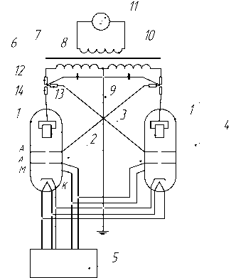
Figure 1 Diagram of the experimental plant
1 – Cathode Ray Tube (CRT), LO-247 type; 2- Electron-beam gun (HCPL) of EBT; 3 - Polarizing electrode (PE); 4 – Vacuum chamber (VC); 5-Power unit (PU) of EBT; 6 – High voltage winding (HVW); 7 - Transformer rectifier ( Т – R); 8 - Midpoint (MP) of HVW; 9 – Equalizing capacitors; 10 - Low-voltage winding (LVW); 11 – Low frequency standard-voltage generator; 12- Измерительный резистор силы тока in LVW; 13 – Current intensity precision resistor in anode circuit А 2 of EBT; 14 - Current intensity precision resistor in circuit of PE.
The research was carried out within the range of 50 Hz - 5 kHz. Measuring and monitoring of electric processes at the plant were performed with dual beam oscilloscope of С 1-99 type. The measurements in each actual frequency were done ten times and the result was averaged. Scattered results were random, they were not more than 7% from the average meaning, and as a consequence, generic issue is averaged. The experiment results are presented by figures 2 and 3.
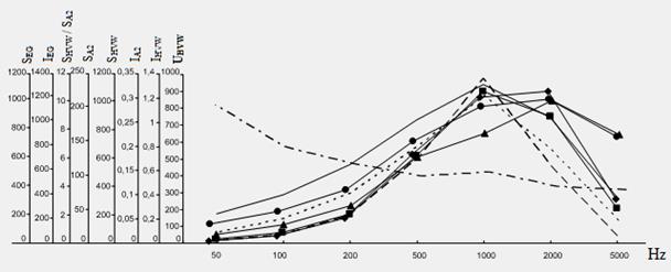
Figure 2. Measurement results of the energy transfer of electron flow interaction of electron plasma into electromagnetic process
![]() UHVW – high voltage winding, V;
UHVW – high voltage winding, V;
![]() IHVW - current intensity of high-voltage winding, A;
IHVW - current intensity of high-voltage winding, A;
![]() IA2 - anode circuit current intensity of the electron gun, mA;
IA2 - anode circuit current intensity of the electron gun, mA;
![]() SHVW - high-voltage winding capacity, mVA;
SHVW - high-voltage winding capacity, mVA;
![]() SA2 - anode circuit current intensity of the electron gun, mVA;
SA2 - anode circuit current intensity of the electron gun, mVA;
![]() SHVW / SA2 – ratio of high voltage winding capacity to anode circuit current intensity of the electron gun;
SHVW / SA2 – ratio of high voltage winding capacity to anode circuit current intensity of the electron gun;
![]() IEG – current intensity of electron generator, mA;
IEG – current intensity of electron generator, mA;
![]() SEG – electron generator power, mVA.
SEG – electron generator power, mVA.

Figure 3. Measurement results of the energy transfer of electron flow interaction of electron plasma into electromagnetic process with equalizing capacitors
![]() UHVW – high voltage winding electric potential, V;
UHVW – high voltage winding electric potential, V;
![]() IHVW - high-voltage winding current intensity, A;
IHVW - high-voltage winding current intensity, A;
![]() IA2 - anode circuit current intensity of electron gun, mA;
IA2 - anode circuit current intensity of electron gun, mA;
![]() SHVW - high-voltage winding capacity, mVA;
SHVW - high-voltage winding capacity, mVA;
![]() SA2 - anode circuit capacity of electron gun, mVA;
SA2 - anode circuit capacity of electron gun, mVA;
![]() SHVW / SA2 – Ratio of high voltage winding capacity to anode circuit capacity of electron gun;
SHVW / SA2 – Ratio of high voltage winding capacity to anode circuit capacity of electron gun;
![]() IEGCC – current intensity of electron generator with compensating capacity, mA;
IEGCC – current intensity of electron generator with compensating capacity, mA;
![]() SEGCC - the power of electron generator with compensating capacity, mVA.
SEGCC - the power of electron generator with compensating capacity, mVA.
2. Kazmin, B.N., Trifanov I.V. "On the possibility of the electronic interaction energy transition into the electromagnetic process energy" // International Journal ISSN 1608 - 8298. "Alternative Energy and Ecology», № 2, 2012. – Pp. 183 - 186. [In Russian]
3. Shimony, K. Theoretical electrical engineering. “Mir”, Moscow, 1964. [In Russian]
4. Kazmin, B.N., Trifanov I.V. About electronic generator of electric energy // Scientific Journal “SibSAU Vestnik”. Vol. 1 (34) Krasnoyarsk, 2011. - Pp. 25-28.
5. Kazmin, B.N., Trifanov I.V. On the possibility to design electron source of electric energy // Scientific Journal “SibSAU Vestnik”. Vol. 2 (35) Krasnoyarsk, 2011. - Pp. 30-34.
6. Kazmin, B.N., Trifanov I.V. et al. Electrodynamic propulsion plant. Patent RU №2453972, Bulletin № 17, 20.05.2012.
7. Kazmin, B.N., Trifanov I.V., Kovalchuk V.B., Ryzhov D.R., Homenko I.I. Experimental testing electron plasma interaction energy transition into electromagnetic process to create electroenergetic technology. // International Journal ISSN 1608 - 9298. "Alternative Energy and Ecology», № 11, 2012. [In Russian]
Kazmin B.N., I.V.Trifanov, M.V. Savelyeva, D.R. Ryzhov THE ALTERNATIVE ENERGY YIELD OUT OF ELECTRON PLASMA FLOW. International Journal Of Applied And Fundamental Research. – 2013. – № 2 –
URL: www.science-sd.com/455-24174 (22.07.2026).