


About Us
Executive Editor:Publishing house "Academy of Natural History"
Editorial Board:
Asgarov S. (Azerbaijan), Alakbarov M. (Azerbaijan), Aliev Z. (Azerbaijan), Babayev N. (Uzbekistan), Chiladze G. (Georgia), Datskovsky I. (Israel), Garbuz I. (Moldova), Gleizer S. (Germany), Ershina A. (Kazakhstan), Kobzev D. (Switzerland), Kohl O. (Germany), Ktshanyan M. (Armenia), Lande D. (Ukraine), Ledvanov M. (Russia), Makats V. (Ukraine), Miletic L. (Serbia), Moskovkin V. (Ukraine), Murzagaliyeva A. (Kazakhstan), Novikov A. (Ukraine), Rahimov R. (Uzbekistan), Romanchuk A. (Ukraine), Shamshiev B. (Kyrgyzstan), Usheva M. (Bulgaria), Vasileva M. (Bulgar).


Engineering
 PDF
PDFIntroduction
Fuel gas consumption of utility units and process units at a natural-gas processing plant (NGPP) depends on scheme, type of process, production capacity, operation moods, condition of equipment, maintenance, rate of combustible waste (CW) recovery, regional factor. It is 17-94 m3 per 1000 m3 of produced gases and it tends to increase during last few years. A fuel utility system is a part of an energy utility section of NGPP. The feature of the fuel utility system is relationship with a process system (PS) and the energy utility system (EUS) through continuous process. This may be explained by the fact that process gases, wastes (fluid wastes with variable composition) are used internally as fuel. That is why methods of optimization and management of the fuel utility system and the EUS as a whole are due to maximum usage of CW internally. It allows to reduce the need for fuel for process units and energy units (e.g. electricity, hot, cold generation). In addition internal usage of CW reduces import energy resources such as electricity, steam. Due to this energy consumption of external energy sources is reduced.
Optimizing of the fuel utility system is done in the following stages:
– design of a structure of object, goals and methods of researches;
– selection and justification of energy efficiency indicators;
– development of software models and algorithms;
– creation (synthesis) of optimal EUS;
– development of technique able to improve energy efficiency of EUS according to unique scheme and processes.
A structure of the fuel utility system.
The design of the structure of the fuel utility system is the first step to achieve the goal of optimization of fuel consumption. It is based on top-down approach and disaggregation methods of analysis of a complex system.
In outline process scheme of the NGPP is presented in Figure 1 below. This scheme is appropriate for NGPP processing variable raw materials – gas, gas condensate and producing wide range of commercial products.
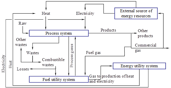
Figure 1. The scheme of relationships between fuel utility system, energy utility units,
process units and external energy supply system
A matrix-model shows interrelations of gaseous flows with process units and utility units as illustrated in Table 1 below.
Table 1. The matrix of relation between gaseous flows, process units, utility units
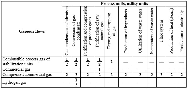
1 – production of energy resource, 2 – consumption of energy resource
The problem of fuel utility system optimization in general form is represented as a careful energy and material balance (EMB) with maximum usage of internal energy recourses and CW. Model-based method has been used for development of EMB and calculation of energy efficiency indicators of a fuel utility system according to its structure and the matrix of gaseous flows. An information graph has been developed for the NGPP with conversion of raw materials, recirculation of intermediate product, internal production of electricity and heat. This is illustrated in Figure 2.
Converting indices of the graph correspond to the following energy and process flows: ![]() - process flows;
- process flows; ![]() and
and ![]() - fuel flows;
- fuel flows; ![]() - heat flows.
- heat flows.
Generally mathematic description of fuel generation or consumption depending on variable process, regional, economic factors is presented by the following equations:
Production of commercial gas (![]() ) and process gases (
) and process gases (![]() ) at process units:
) at process units:
![]() ; (1)
; (1)
fuel consumption (commercial gas and process gas) at process units:
![]() ; (2)
; (2)
fuel consumption from an internal source of heat and electricity – auxiliary power units (APU) for steam production:
![]() ; (3)
; (3)
heat production in waste-heat boilers (WHB) of process units:
![]() ; (4)
; (4)
heat consumption of NGPP from an external source (a boiler house):
![]() ; (5)
; (5)
fuel consumption in a boiler room for heat generation to NGPP and auxiliary energy consumption:
![]() . (6)
. (6)
Where:
![]() - lower heating value of gas used in a boiler room;
- lower heating value of gas used in a boiler room; ![]() - energy efficiency of boiler units of an external energy source;
- energy efficiency of boiler units of an external energy source; ![]() - coefficient of auxiliary energy consumption in a boiler room
- coefficient of auxiliary energy consumption in a boiler room
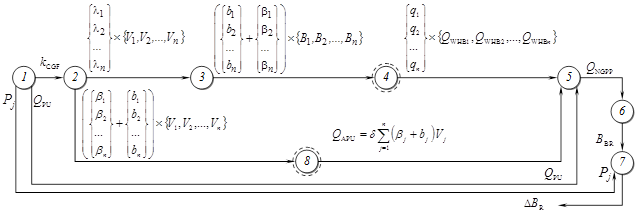
Figure 2. Informational graph of calculation GPP energy-balances and fuel consumption of external energy-source:
tops: 1 – initial data; 2 – material balance; 3 – fuel-balance of processing and utility systems; 4 – heat-balance of waste-energy utilization system PS and EUS; 5 – heat-balance of NGPP; 6 – heat and fuel balances of boiler room; 7 – energy balance of system of steam compression; 8 – heat and fuel balances of auxiliary power units (APU)
initial data and variables: ![]() ,
, ![]() – heat consumption of process units, steam pressure at the current level of energy utility system;
– heat consumption of process units, steam pressure at the current level of energy utility system; ![]() ,
, ![]() – process and fuel flows;
– process and fuel flows; ![]() – condensate-gas factor (ratio of gas condensate amount to total volume of process gas);
– condensate-gas factor (ratio of gas condensate amount to total volume of process gas); ![]() ,
, ![]() ,
, ![]() – WHB thermal output, APU thermal output, heat consumption of NGPP from the boiler room;
– WHB thermal output, APU thermal output, heat consumption of NGPP from the boiler room; ![]() – fuel consumption in a boiler room;
– fuel consumption in a boiler room; ![]() – fuel lost from high-pressure steam reducing to pressure in boiler room
– fuel lost from high-pressure steam reducing to pressure in boiler room ![]()
Perfect structure and operation mode of PS and EUS is absence of import of heat. The equation (5) may be expressed as: ![]() . It can be realized by CW using as a fuel in auxiliary power units.
. It can be realized by CW using as a fuel in auxiliary power units.
Mathematical models of units of CW utilization and units of heat, cold, electricity production have been designed. These models have to consider schemes and operation factors as much as possible accurately. For example, consider the fuel utility system of a facility of NGPP. The facility recovers CW and generates heat by WHB and cold by absorption heat transformer (AHT). Schematic diagram is illustrated in Figure 3 below.
The amount of additional fuel from commercial net depends on: CW performance,![]() , heating value of CW,
, heating value of CW, ![]() ; heating value of fuel gases,
; heating value of fuel gases, ![]() ; cooling output AHT (thermal output of the evaporator),
; cooling output AHT (thermal output of the evaporator), ![]() ; heat load of heat consumer,
; heat load of heat consumer, ![]() ; temperatures in AHT – higher (into the generator)
; temperatures in AHT – higher (into the generator) ![]() , lower (into the evaporator)
, lower (into the evaporator) ![]() , medium (cooling fluid in the cooler)
, medium (cooling fluid in the cooler) ![]() ; coefficient of heat saving of the cyclone burner
; coefficient of heat saving of the cyclone burner ![]() , the WHB
, the WHB ![]() , the generator AHT
, the generator AHT ![]() .
.
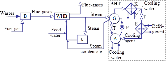
Figure 3. The facility with waste gases utilization and energy (heat, cold) production:
B – cyclone burner; WHB – waste-heat boiler; U – heat user of process units; А, G –absorption and generation units of AHT; K – condenser; T – throttling device; E – evaporator; P – pump
A desired dependency of fuel gas consumption as a function of scheme factors and operation moods has been obtained in according to relationships of items of the facility with waste gases utilization and heat, cold production. The items necessary for definition of the dependency of fuel gas consumption are shown in Figure 4 below.
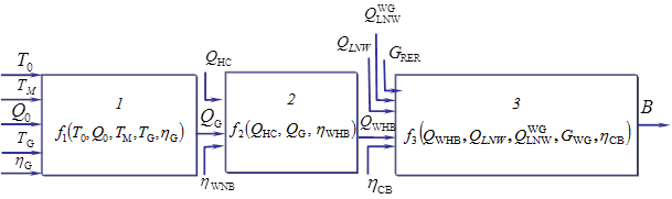
Figure 4. Diagram of the facility with waste gases utilization:
1 – AHT; 2 – WHB; 3 – the cyclone burner; ![]() ,
, ![]() – heat load (heat output/input) of WHB and the generator of the AHT; В – fuel gas consumption
– heat load (heat output/input) of WHB and the generator of the AHT; В – fuel gas consumption
A mathematical formulation of the considered problem is formed as functional dependency and can be defined as:
![]() . (7)
. (7)
The problem has been solved sequentially beginning with the first item (AHT). A dependency ![]() has been defined for AHT. An analytical dependency of an input variable on input shifting factors of process units and a temperature of cooling medium has been obtained. A known equation of specific heat consumption at AHT has been used for finding the analytical dependency. The analytical dependency is given by
has been defined for AHT. An analytical dependency of an input variable on input shifting factors of process units and a temperature of cooling medium has been obtained. A known equation of specific heat consumption at AHT has been used for finding the analytical dependency. The analytical dependency is given by
![]() . (8)
. (8)
A desired dependency ![]() for the second item (WHB) is obtained from an equation of an energy balance of the item. That is:
for the second item (WHB) is obtained from an equation of an energy balance of the item. That is:
![]() , (9)
, (9)
The heat load ![]() is a given value.
is a given value.
A dependency of fuel gas consumption on influencing process factors ![]() for the third item (the cyclone burner) has been found by calculation of an energy balance of this item. That is:
for the third item (the cyclone burner) has been found by calculation of an energy balance of this item. That is:
![]() (10)
(10)
A final equation has been found by substitution formula (8) – (10) into the equation (7). The final equation enables to determine the dependency of fuel consumption on influencing input factors. That is:
 . (11)
Moreover, fuel consumption of process units and utility units depends on production rates of separate units in accordance with their schedule of maintenance or major refurbishment. This operating factor was taken into account as appropriate load factors of units by analytical models of calculation.
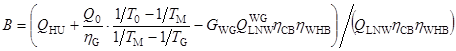
A control algorithm of fuel consumption is based on operation modes of units. The operation modes have been developed by means of analytical models and software.
One of possible type of operation modes for the facility with waste gases utilization and heat, cold production as a phase diagram is shown in Figure 5. As a system parameters the following data were taken: ![]() = 1030 kW,
= 1030 kW, ![]() = 23 MJ/kg,
= 23 MJ/kg, ![]() = 36 MJ/m3,
= 36 MJ/m3, ![]() = 0,05 kg/s,
= 0,05 kg/s, ![]() = 303 К,
= 303 К, ![]() = 413 К.
= 413 К.
Operation modes of boilers and external source of heat in accordance with changing load factors of NGPP are formed according to the equations (1) – (6). Achievement of the controlling goal for NGPP processed sulfur-rich raw gas is shown in Figure 6. Finally dynamic dependencies (function of raw materials load) are defined. The dynamic dependencies are production capacity of the boiler room and quantity of working boilers.
Design solutions of increasing the efficiency of fuel utility system through recovering CW are implemented in creating process units of absorbent recovery [4, 5] and internal source of energy and water supply with high extent using of wastewater and secondary energy resources [6].
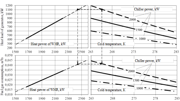
Figure 5. The phase diagram of the facility with waste gases utilization and energy production
Simulation of operation conditions of the process units of NGPP in operation enables to obtain the significant data. For example, the development of a dehydration unit with the help of implementation of energy efficient facility of absorbent recovery enables to reduce fuel gas consumption by 30-36%. Specific fuel gas consumption (to 1000 ![]() drying gas) is 0.317
drying gas) is 0.317![]() , that is less than 0.178
, that is less than 0.178![]() . For the unit with production capacity (recycled absorbent) of about
. For the unit with production capacity (recycled absorbent) of about ![]() t/yr. savings will be 28000 EUR, payback will be less than 2.5 years.
t/yr. savings will be 28000 EUR, payback will be less than 2.5 years.
Figure 6. Operation moods of the boiler room under variable production rate
The implementation of an internal source of energy and water supply with CW utilization for large NGPP enables to reduce 12-14% of specific year fuel consumption for production of 1MW. Ten year savings in accordance with the type of plant are 122000-277000 EUR per MW. Internal rate of return (IRR) is 22-26%; payback is 7-9 years.
Conclusions. Developed optimization and management methods of EUS of process industries, models of material and energy balances calculation in accordance with process factors, operation conditions enable to design main directions and specific technical solutions for using CW as a fuel. Altogether, it will result in reducing energy consumption from external sources and reducing fuel consumption at all.
This work was supported by the Ministry of Education and Science of the Russian Federation, project no. 1579, within the framework of a state assignment.
[2] I.V. Dolotovskij, N.V. Dolotovskaja, E.A. Larin. Software for Optimisation and Rational Consumption and Production of Fuel, Energy Resources at Production Site // Patent RU№ 2465639. 2012, Bul. №30.
[3] I.V. Dolotovskij, N.V. Dolotovskaja, E.A. Larin. System “EnerguResource”// Software № 2010615353, 20.08.10.
[4] I.V. Dolotovskij, A.V. Lenkova. Unit of Absorbent Recovery with thermal utilization of Combustible Wastes // Patent RU № 114424. 2012, Bul. № 9.
[5] I.V. Dolotovskij, N.V. Dolotovskaja. Unit of Methanol Recovery with thermal utilization of Combustible Wastes // Patent RU № 138474. 2014, Bul. №8.
[6] I.V. Dolotovskij. Unit of Electricity, Heat and Water Supply of Hydrocarbon Raw Processing Sites // Patent RU № 118360. 2012, Bul. №20.
Dolotovskij I.V., Lenkova A.V., Dolotovskaja N.V., Larin E.A. OPTIMISATION AND MANAGEMENT OF ENERGY UTILITY SYSTEM OF NATURAL GAS PROCESSING PLANT. International Journal Of Applied And Fundamental Research. – 2015. – № 1 –
URL: www.science-sd.com/460-24776 (23.07.2026).